
Calibration and test system for Fluke infrared temperature sensors: 40 sensors per batch
EPSIA delivered a calibration and test system for a range of infrared temperature sensors made by Fluke Process Instruments. The system processes up to 40 sensors per batch in around 1.5 hours. Different sensor types are configured through their stored process parameters, so the system does not need a mechanical changeover for each type.
EPSIA took on the project as general contractor: from concept and system architecture, through coordination of mechanical design and electrical engineering, to control engineering, control software, system integration and commissioning. Dedicated sensor boards were developed by an external engineering firm to EPSIA's specifications. Software development started on the digital twin before the real system was fully available.
- 40sensors per batch in around 1.5 hours
- 27calibrated sensors per hour instead of 10 on the previous system
- 8radiant heaters with setpoints specific to each sensor type
- 4control loops for the sensors' ambient temperature
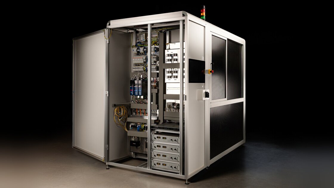
The case study follows the project in seven steps: brief, digital twin, system, sensor electronics, calibration sequence, different sensor types and result.
1 Brief: one calibration system for different sensor types
Since 2021, Fluke has calibrated infrared temperature sensors on a calibration machine for MI3 sensors whose control software was developed by EPSIA. The successor system was to calibrate and test different sensor types from the manufacturer on one shared system, hold more sensors per batch and increase throughput.
One technical limitation of the previous solution was the communication box used to address the individual sensors. Communication with the sensors was therefore also to be redesigned for the new system.
Fluke commissioned EPSIA with the complete system. The main contract was carried out on the basis of a functional specification as a fixed-price project with four milestones. Extensions for additional sensor types and later work on the sensor fixture followed under separate contracts.
2 Digital twin: software development before the hardware was available
EPSIA developed the control software against a 3D simulation of the system in Unity. This allowed the user interface, machine sequences and parts of the control logic to be developed and agreed with Fluke while motors and control components still had lead times of several months in 2022.
The software architecture separates the machine logic from the specific hardware connection. During development, the control software could therefore be connected to the digital twin, to lab set-ups and later to the real components of the system.
As the machine took shape, EPSIA replaced the simulated components step by step with real hardware. The first production run on the system took place in March 2024.
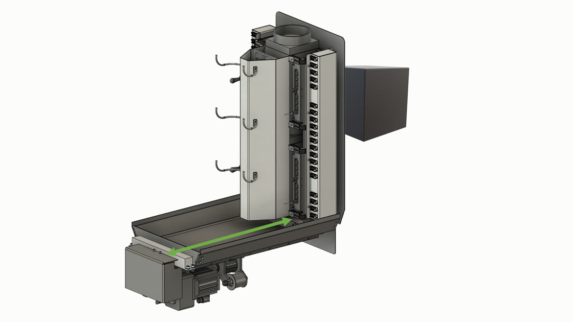
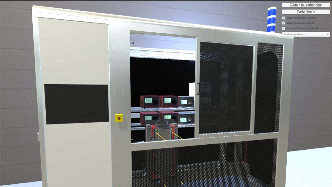
3 System: all process components controlled by one overall system
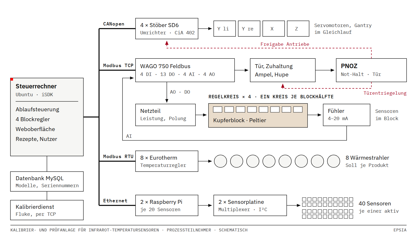
The central control software runs on a PC with iSDK, the platform developed by EPSIA. Several bus systems connect the controller to drives, radiant heaters, I/O components and sensor electronics.
- Drives
- Four Stöber servo inverters via CANopen. A gantry axis runs with two synchronised motors, plus an X and a Z axis. The travel ranges are up to 1,330, 890 and 400 mm.
- Radiant heaters
- Eight radiant heaters with Eurotherm controllers via Modbus RTU. The previous system worked with five heaters.
- Ambient temperature
- A system of copper blocks and Peltier elements built by Fluke brings the sensors to temperature. EPSIA developed its control with four control loops.
- I/O and safety
- WAGO I/O via Modbus TCP connects door states, guard locking, signal lights and control loops, among others, to the control software. Safety functions such as emergency stop and door monitoring are implemented independently through a PNOZ safety relay.
- Sensor communication
- Two sensor boards, each with a Raspberry Pi, connect the controller to up to 20 sensors each.
- Data
- A MySQL database manages sensor types, process parameters and serial numbers, among other data. The calibration curves are calculated by a Fluke calibration service.
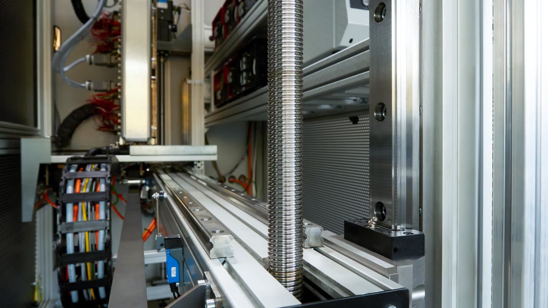
4 Sensor electronics: addressing 40 sensors individually
Each sensor has its own microcontroller, and all of them use the same I²C address. Holding up to 40 sensors in parallel therefore required a new communication solution.
EPSIA developed the concept and requirements for two dedicated sensor boards. An external engineering firm handled electronic design and manufacturing on EPSIA's behalf.
Each board connects up to 20 sensors to a Raspberry Pi. Multiplexers switch onto the communication bus the sensor the software needs to talk to at that moment. The Raspberry Pi handles the low-level communication and is connected over the network to the central system controller.
This lets the system read measured values, assign serial numbers and write calibration curves and derating data for each individual sensor. The written data is then read back for verification.
5 Calibration sequence: processing a batch largely automatically
Once a batch has been loaded and started, the system carries out the calibration and test steps automatically. Time-consuming operations run in parallel wherever possible: the sensors are brought to temperature together while the radiant heaters reach their respective setpoints.
For the actual measurement, the axis system positions each sensor in front of its assigned radiant heater. After the settling time, the system records 200 measured values.
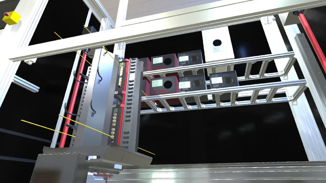
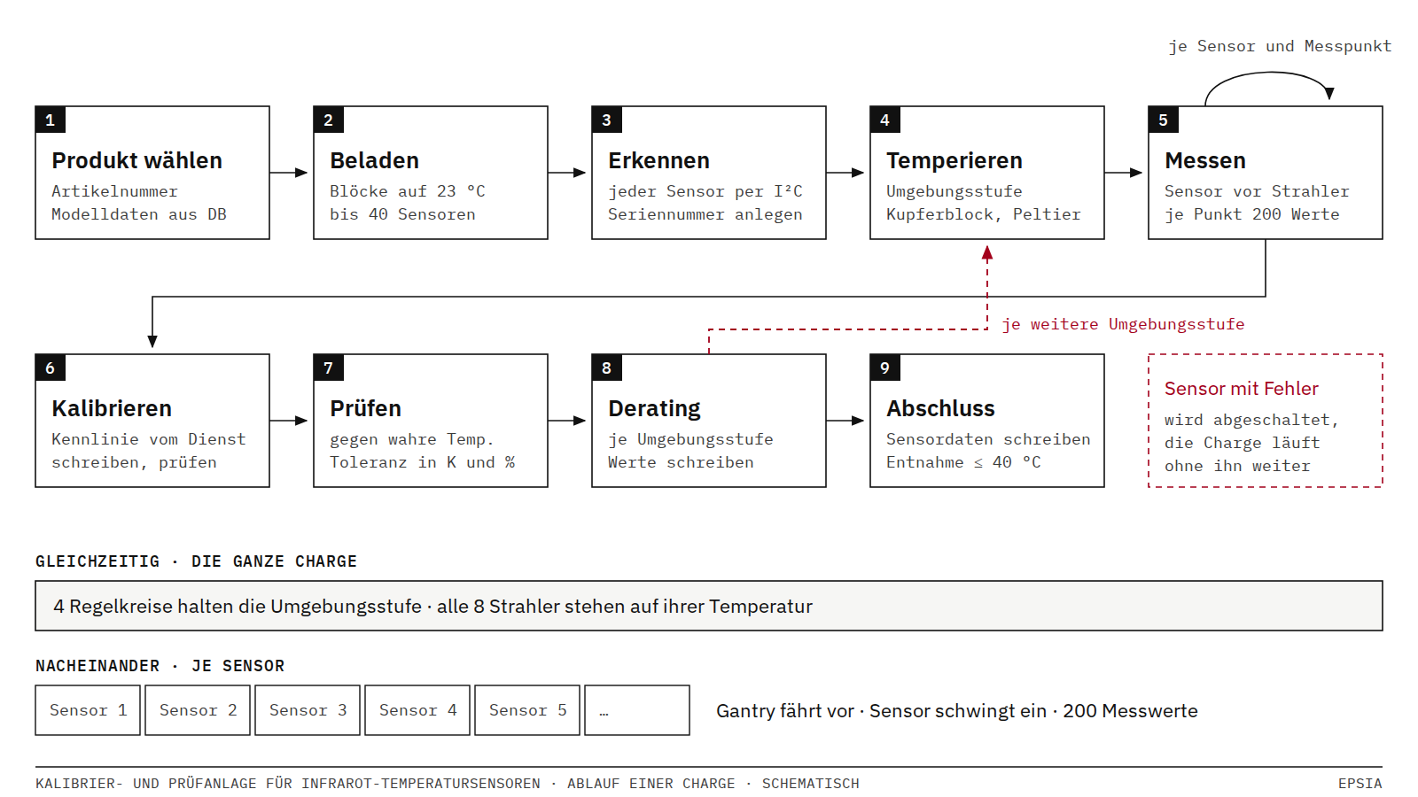
The process includes the following steps, among others:
- Detect sensors
- The system checks which positions are occupied and creates records with serial number and model data for the sensors it detects.
- Calibrate
- Measured values are sent to the Fluke calibration service. The system writes the resulting calibration curve to the sensor and then reads it back for verification.
- Test
- At further temperature points, the software compares the sensor's readings with the reference temperature of the radiant heater and evaluates them against the stored tolerances.
- Determine derating
- For further ambient temperatures, the sensor fixture is brought to a new temperature and the measurement sequence is repeated.
- Handle errors
- If a sensor fails a process step, it is removed from the rest of the sequence with the corresponding cause of failure. The remaining sensors in the batch continue to be processed.
6 Different sensor types: process parameters instead of mechanical rebuilds
In the system, a sensor type is essentially described by its stored process parameters. The operator selects the relevant part number; the software then loads the required ambient, calibration, test and derating temperatures, together with waiting times and tolerances, from the database.
The radiant heaters are set automatically to the temperatures needed for that sensor type. At the same time, the system brings the sensor fixture to the specified ambient temperatures – for one example type, 23 and 80 °C.
The layout of the fixture can also be configured. MI3 sensors, for example, have ten positions per block half; another product line uses eight positions with wider spacing.
EPSIA also developed the temperature control for the sensor fixture. The software first determines the thermal characteristic of each block and uses it for feedforward control. An additional P and I component corrects any remaining deviation.
Because the Peltier elements can heat or cool depending on the direction of the current, the same sensor fixture can reach different ambient temperatures both by heating and by cooling.
7 Result: 40 sensors in around 1.5 hours
The new calibration and test system increases both the capacity per batch and the throughput compared with the previous system.
- Up to 40 sensors are processed in around 1.5 hours. The previous system processes 20 sensors in around two hours.
- This gives a throughput of around 27 instead of 10 sensors per hour – roughly 2.7 times as many.
- Different sensor types can be processed using stored process parameters, without a fundamental mechanical rebuild of the system for each type.
- Eight radiant heaters provide the required reference temperatures.
- Two purpose-built sensor boards allow individual communication with up to 40 sensors.
- The first production run took place in March 2024 and preliminary acceptance in December 2024. The last agreed software version was handed over to Fluke in February 2026.
What does this project stand for?
The project shows how EPSIA can take responsibility beyond software development on a system with a hardware connection. As general contractor, EPSIA coordinated the complete system, worked with specialist partners on mechanical design, electrical engineering and electronics development, and developed the system architecture, control engineering, control software and system integration itself.
The digital twin made it possible to develop and agree the software, operating concept and machine sequences while key hardware components were not yet available. During the build of the system, the simulation was then replaced step by step with real hardware.
How long did it take to handover?
The main contract was carried out as a fixed-price project with four defined milestones. During the supply shortages of 2022, software development continued on the digital twin.
The first production run on the system took place in March 2024 and preliminary acceptance in December 2024. Extensions for additional sensor types and work on the sensor fixture were carried out under separate contracts. EPSIA handed over the last agreed software version in February 2026.
How does a system project with EPSIA start?
A system project with EPSIA can start with an architecture check at an agreed fixed price. In it, EPSIA analyses the hardware connection, machine sequences, interfaces and the requirements for later operation.
The result describes the components needed, how they work together and a sensible order for implementation. On this basis, a functional specification and a fixed-price offer for the subsequent development can be prepared.
For suitable systems, a digital twin can be part of the software architecture and the development process from the start.
More on this service under Software for systems with a hardware connection.
The previous generation is shown in the reference Calibration machine for Fluke infrared temperature sensors.
Key facts
- Customer
- Fluke Process Instruments, Berlin
- Service
- Hardware-related systems
- Industry
- industrial measurement and non-contact temperature measurement
- Period
- 2021 to 2026, main contract at a fixed price, later extensions under separate contracts
- Technology
- C++, Qt, iSDK, JavaScript, Python, Unity, MySQL, CANopen, Modbus RTU, Modbus TCP, WAGO I/O, I²C, Raspberry Pi, Eurotherm controllers.