
Calibration machine for Fluke infrared temperature sensors: more than 80,000 sensors since 2021
EPSIA developed the complete control software for a calibration machine at Fluke Process Instruments. The machine calibrates, tests and certifies MI3 series infrared temperature sensors in a largely automated process.
Up to 20 sensors are processed together as a batch – from reading in and identification through several temperature measurements and individual calibration to validation and the calibration certificate.
- 80,000+sensors calibrated, tested and certified since 2021
- 20sensors per batch in around 2 hours
- 71,426lines of C++ code generated from the machine description
The case study follows the project in seven steps: order, machine, process, machine description, commissioning, relocation and result.
1 Order: Automating calibration and testing
Before delivery, every infrared temperature sensor must be measured at several temperatures, individually calibrated and then tested. At Fluke, these steps were previously carried out partly by hand, with a semi-automatic machine or on an existing system.
The goal of the new system was an automated, reproducible process for complete sensor batches. Measured values and calibration data were to be stored traceably for every single sensor.
EPSIA analysed the requirements and wrote the functional specification for the control software in August 2020. After a concept phase, the subsequent development was carried out as a fixed-price project with three defined milestones.
Why do infrared temperature sensors need to be calibrated?
Infrared temperature sensors determine the temperature of an object from its thermal radiation, without touching it. Optics and detector convert the captured infrared radiation into an electrical signal from which the temperature is calculated.
Because manufacturing tolerances make each sensor slightly different, every sensor needs an individual calibration. It is measured at known temperatures, and a characteristic curve is derived from the measured values. The effect of different ambient temperatures on the measurement must also be taken into account.
2 Machine: Radiant heat sources, sensor fixture and two servo axes
The machine combines up to six radiant heat sources with a heated fixture for up to 20 sensors. Two servo axes position the heat sources in front of the sensors to be calibrated, one after another.
The heat sources provide defined reference temperatures, while the heated fixture creates different ambient temperatures for the sensors. EPSIA's control software coordinates all the components involved:
- Sensors, heat sources and heaters: communication via RS485.
- Servo axes: control via CANopen.
- Door, emergency stop, buttons and signal lights: WAGO I/O via Modbus.
- Data storage: measurement, calibration and process data are stored in a MariaDB database.
If a single sensor fails during a batch, the software can remove it from the rest of the process and continue processing the remaining sensors.
3 Process: From loading to calibration certificate
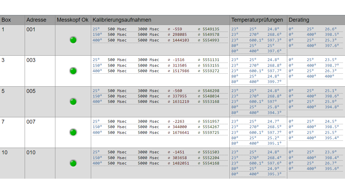
EPSIA automated the complete calibration and test process for a batch of up to 20 sensors:
- Loading: The operator inserts the sensors and scans their barcodes. The software checks that the sensors belong to the intended product type.
- Identification: The software reads out the sensors. New sensors are assigned a serial number, which is stored on the sensor together with the product information.
- Setting temperatures: The heat sources and sensor fixture are brought to the temperatures required for each test step. Heat-up times and correction values for different heat source types and distances are stored in the software.
- Taking temperature measurements: As soon as stable conditions are reached, the servo axes position the heat sources in front of the sensors one after another and the measured values are recorded.
- Calibration: A calibration service calculates each sensor's individual characteristic curve from the measured values. The resulting calibration data is then written to the sensor.
- Validation: The calibrated sensors are measured again at defined temperatures and checked against the product-specific tolerances. In addition, their behaviour at different ambient temperatures is examined and corrected.
- Certification: For every sensor that passes, the software automatically generates a calibration certificate as a PDF. Measured values and process data remain traceable in the database.
4 Machine description: 1,938 lines become 71,426 lines of C++
EPSIA describes key parts of the machine declaratively. Modules, parameters, events and operator dialogues are defined in a structured machine description.
From this, iSDK, the base system developed by EPSIA, automatically generates large parts of the control system's C++ source code. For this machine, 1,938 lines of machine description produce 71,426 lines of generated C++ code. When something changes, this code can be regenerated reproducibly.
Recurring structures of the machine control therefore do not have to be programmed individually, and they follow the same technical rules throughout the system.
Scope of the machine software
- Machine description
- 1,938 lines in 24 files, 17 asynchronous modules, 42 operator dialogues
- Generated from it
- 71,426 lines of C++ code in 228 files
- Developed by hand
- 12,770 lines of code in 152 files
- iSDK base system
- 88,562 lines of code
- Total
- 172,758 lines of code, 960 classes, 3,356 changes
- Axes
- 2 servo axes via CANopen
- Temperature sources
- up to 6 heat sources and 2 block heaters via RS485
- Sensors
- up to 20 per batch via RS485
- I/O signals
- 15, via WAGO/Modbus
5 Commissioning: Acceptance in September 2021
EPSIA commissioned the machine at Fluke Process Instruments' Berlin plant. Acceptance of the last agreed milestone took place in September 2021.
The user interface includes user and permission levels, recipe management and commissioning functions, among other things. EPSIA also developed tools for database access, analysis, motor tests and diagnosing individual sensors.
6 Relocation: From Berlin via the UK to China
After its original use in Berlin, Fluke moved the calibration machine first to the UK and later to China. EPSIA's control software continued to run at the new sites.
For operation in the changed IT environment, EPSIA developed a new Windows installer in 2025, among other things. Further functions were added over the years of operation, including automatic generation of the calibration certificates.
The software has thus accompanied the same machine across several production sites and different technical operating environments.
7 Result: More than 80,000 sensors since 2021
Since delivery in 2021, more than 80,000 infrared temperature sensors have been calibrated, tested and certified with the calibration machine.
- Up to 20 sensors are processed together in one batch.
- A batch takes around two hours, roughly 30 minutes less than with the previous method.
- Calibration and testing are reproducible and follow the stored product specifications.
- Measured values and calibration data are stored traceably for every sensor.
- Calibration certificates are generated automatically from the recorded data.
- The machine has been moved to another production site twice and is operated in China today.
What does this project stand for?
The project shows how EPSIA maps a complex test and calibration process end to end in software: from communication with sensors and temperature sources through motion control and calibration logic to data storage and automatic generation of certificates.
The control software was not developed just for the original commissioning. It has supported the machine in production since 2021 and has been adapted to new requirements and several relocations.
How long did it take to reach acceptance?
It took just over a year from the functional specification in August 2020 to acceptance of the last milestone in September 2021.
The project started with a clearly bounded concept phase. The subsequent development was carried out as a fixed-price project with three defined milestones.
How does a system project with EPSIA begin?
A system project with EPSIA can start with an architecture check at an agreed fixed price. In it, EPSIA analyses the hardware connection, machine sequences, interfaces and requirements for later operation.
The result describes the software components needed, how they interact and a sensible order for implementation. On this basis, a functional specification and a fixed-price quotation for the subsequent development can be drawn up.
More about this service under Software development for hardware systems.
Another reference shows the follow-up calibration and test system for infrared temperature sensors, which was designed for different sensor types.
Key facts
- Customer
- Fluke Process Instruments
- Service
- Hardware-related systems
- Industry
- Industrial measurement and non-contact temperature measurement
- Period
- 2020 to 2025, fixed-price project with concept phase and three milestones
- Technology
- C++, Qt 5, iSDK, CANopen, RS485, Modbus, WAGO I/O, MariaDB, JavaScript, Electron, Python, Ubuntu Linux.